MC-4 controller over mechanical fuel dispensers


MC-4 controller over mechanical fuel dispensers is intended to be used in conjunction with a control system for petrol station (POS system, cash register, OPT terminal, etc) to provide direct control over operation of electronic and mechanical fuel dispensers by controlling dispenser’s internal resources: motor, pulse sensor, nozzle, slowdown valve.
Technical characteristics #
| PARAMETER | VALUE |
|---|---|
| Power supply voltage | 12 V DC |
| Current consumption | 300 mA max |
| Temperature range | from -30°C to +60°C |
| Weight | 230 g |
| Overall dimensions | 145 x 100 x 20 mm |
| Interface |
|
| Input communication protocol | UniPump |
| Control | Simultaneous control over 4 nozzles of delivery dispensers:
|
| Signals received |
|
| Maximal ordered and dispensed doze | 9999,99 liters |
| Maximum volume total counter values | 999999,99 liters |
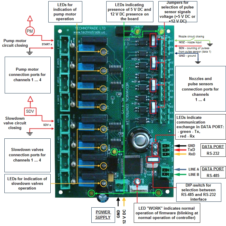
Board overview #
 Click on image to enlarge
Frequently asked questions #
What are the installation requirements for the petrol station?
WARNING! Manufacturer guarantees reliable and stable operation of products only at compliance with below requirements. In case of absence of uninterruptible power supply or incorrect wiring of products to it any claims to malfunction of software are not accepted.
1. Requirements to power supply
The described products come into structure of control system (POS) for petrol station. Power supply of the products should be done from a separate power supply with built-in filter of radio frequency interferences and limiter of high voltage pulse interferences. Power supply should have a safety factor of 1.5.
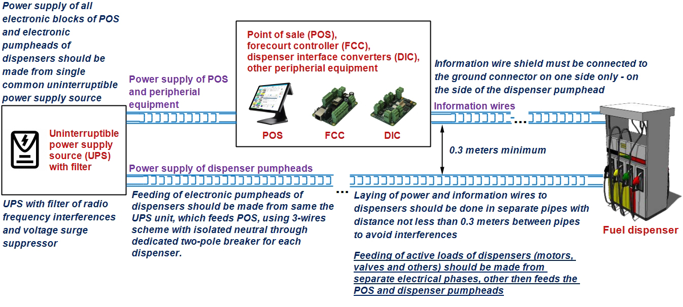
At emergency switching off the power supply or in case of power voltage exceeding its permitted ranges the products can switch off with loss or corruption of data and possible damage of hardware and software. Power supply of all electronic blocks of POS and electronic pumpheads of dispensers, which are connected through information lines, should be made from single common uninterruptible power supply source (UPS). Connection of other devices to given UPS is strictly prohibited. UPS should be of continuous action (online) and work with double conversion with output voltage regulation. UPS should have a safety factor of 1.5. Filter of radio frequency interferences and limiter of high voltage pulse interferences should be used for feeding equipment from UPS.
Supply of electronic pumpheads of dispensers should be made from the UPS unit using 3-wires scheme with isolated neutral through dedicated two-pole breaker for each dispenser. Connection of other parts of dispenser to UPS unit (expect electronic pumpheads) is strictly prohibited.
UPS unit should be connected to a separate three-pole socket fed through the three-wire feeder (phase, neutral, ground wires) with insulated neutral from a dedicated circuit breaker of switchboard. Feeder coming from the switchboard to the socket should located not closer than 0.3 meters to other feeders. The socket should be located at a distance of not more than 1 meter away from the POS. Phase wire of the feeder should not have any other consumer, which are sources of interferences (for example motors).
For protection of POS and UPS from secondary effects of atmospheric electricity it is required to install high-voltage arresters (dischargers) at the transformer substation or on poles of power lines.
2. Requirements to grounding
In the switchboard the ground wire of feeder socket should be connected to the grounding screw, which should be connected by means of welding with a protection grounding circuit of petrol station by steel wire with a diameter of not less than 5 mm.
Protection grounding circuit of petrol station should correspond to safety requirements and be separated from the station lightning protection circuit. Distance from the nearest electrode of protection grounding circuit to electrode of lightning protection circuit must be at least 10 meters. Resistance of the protection grounding circuit should be not more than 4 Ohms and must be confirmed by the test report. Length of wires from the switchboard to the nearest electrode of protection grounding circuit should not exceed 15 meters.
3. Requirements to laying of cable communications
Laying of power and information wires to dispensers should be done in separate pipes with distance of not less than 0.3 meters between each other. For informational wires (current loops, RS-485, other interfaces) it is recommended to use shielded twisted-pair cables (recommended type – FTP CAT 5E). The cable shield must be connected to the ground connector on one side only – on the side of the dispenser.
Controller over mechanical dispensers is to be located inside the fuel dispenser. It connects to dispenser internal resources: motor, pulse sensor, nozzle, slowdown valve. Controller can work in parallel with the dispenser existing electronics with indicators.
Current version of the controller allows connection of up to 4 dispensing nozzles to one controller.
As the controller is to be installed inside the dispenser and distance between the controller and dispenser is quite short - so you can use any standard wires to connection. Connection of the controller to external control system is to be made using any standard FTP cable with twisted pair and aliminium foil for screening (like FTP CAT 5E). Controller is supplied without any cables for connection, all cables are to be taken locally.
Controller over mechanical dispensers uses 12 V DC for feeding. Maximum current consumption is 300 mA.
Power supply source is not supplied together with the controller. The power supply should be selected locally. This is connected with a reason that different countries may have different electricity network specifics: frequency and voltage.
At selection of the power supply you need to pay attention to the following 2 factors:
- output voltage of power supply should be 12 V DC
- maximum allowed current consumption of power supply should be more that maximum current consumption of the controller. If several devices are connected to the same power source - then their total current consumption should be less than maximum allowed current consumption of power supply.
Controller uses the UniPump communication protocol. Its description can be sent upon request.
Order information #
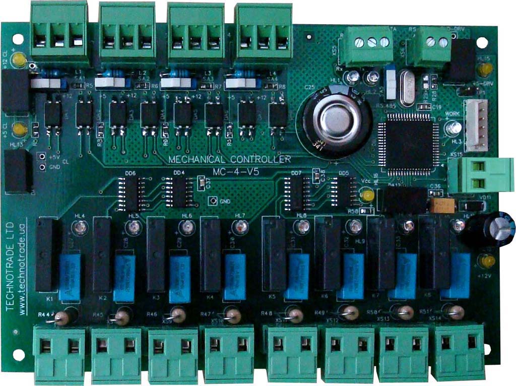 MC-4 controller PCB board with terminal blocks
Order code: MC4-PCB-001
 MC-4 controller in mounting box
Order code: MC4-BOX-001
Ask YOUR questions about
"MC-4 controller over mechanical fuel dispensers"
Other products of section:


|
U2L converter
U2L converter converts from IFSF protocol with LON interface to Tokheim UDC protocol with RS-485/RS-232 interface and backwards, it is intended for communication of POS systems and controller with dispensers, which use LON interface and IFSF protocol, through interfaces: RS-232, RS-485, RS-422.

|
L2D converter
L2D converter converts from IFSF protocol with LON interface to any dispenser, which supports DART protocol with RS-485 interface and backwards. It allows POS systems and forecourt controllers, which use only IFSF-LON to communicate with any dispenser using DART communication protocol.